Eken M001 teardown & serial console
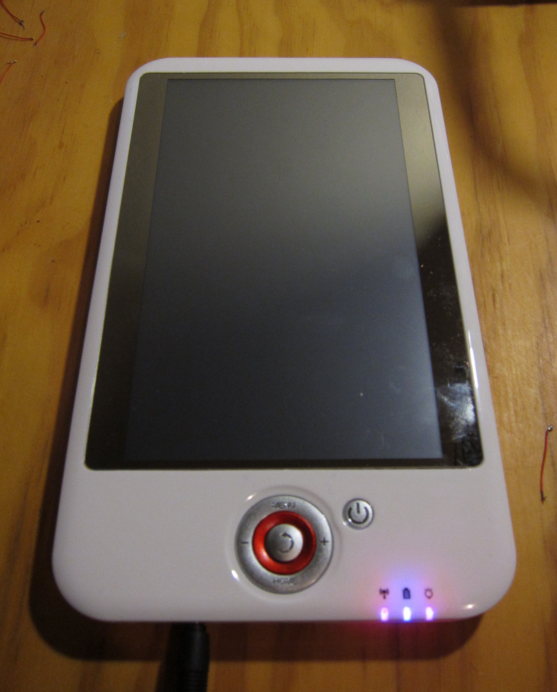
See here for my review of the M001.
This teardown shows the V006 revision of the board, a quick serial port install, and includes some console/dmesg output. The main difference between V005 and V006/V007 board revisions seems to be relocating the USB WiFi dongle to a better position.
EDIT: It took me a while to post this article, and Slatedroid is down this past week. So links to there will be broken (hopefully not for good.)
This isn’t the first teardown of the Eken M001, the first one was the “Aimless Teardown” and there is also a disassembly howto video by another community member.
Warning
I’ve had lots of hardware problems with my Eken since I took it apart. They may have been there before, but maybe not. YMMV, but be careful and remember you may not still have a warranty after the device has been opened, and especially after it’s been modified.
Specifically, I have two problems. There is a cold solder joint in one corner of the board (I’m currently warming it up before it will boot at all.) Also I get occasional failure of the LCD (totally black) on reassembly, which requires me to press on the front of the unit until it clicks back on.
Getting In
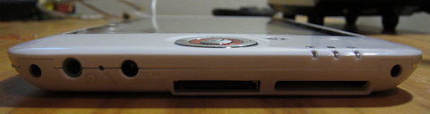
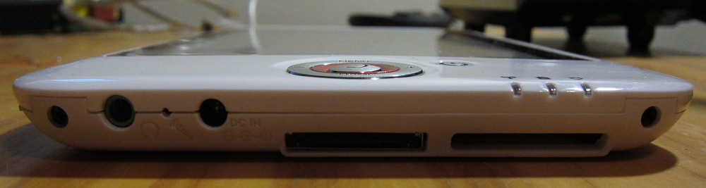
- Remove the two phillips screws on each side of the base:
-
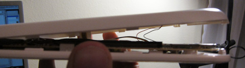
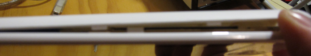
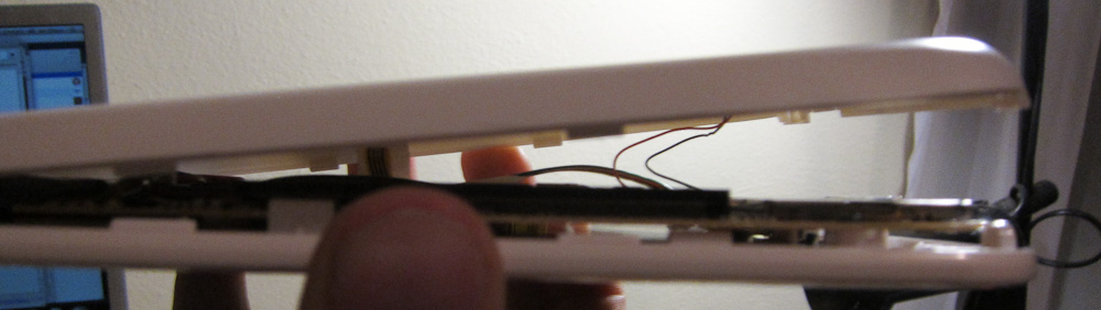
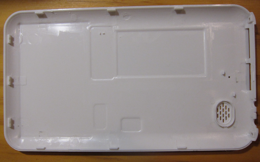
The only other thing holding the back on is a series of plastic clips around the outside of the unit. Working from the base (the first clip is half-way between the two screws), carefully insert a plastic spudger or a knife (worse, but what I used) and jiggle it around until each clip snaps open. Some clips may break, they’re not very strong.
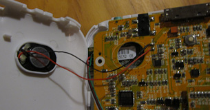
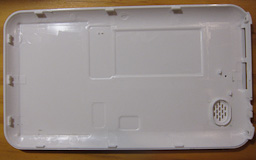
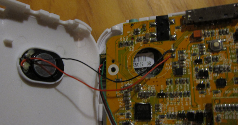
- Once all the clips have popped, remove the plastic back. Take care not to disturb the small speaker

Main Board
![]()
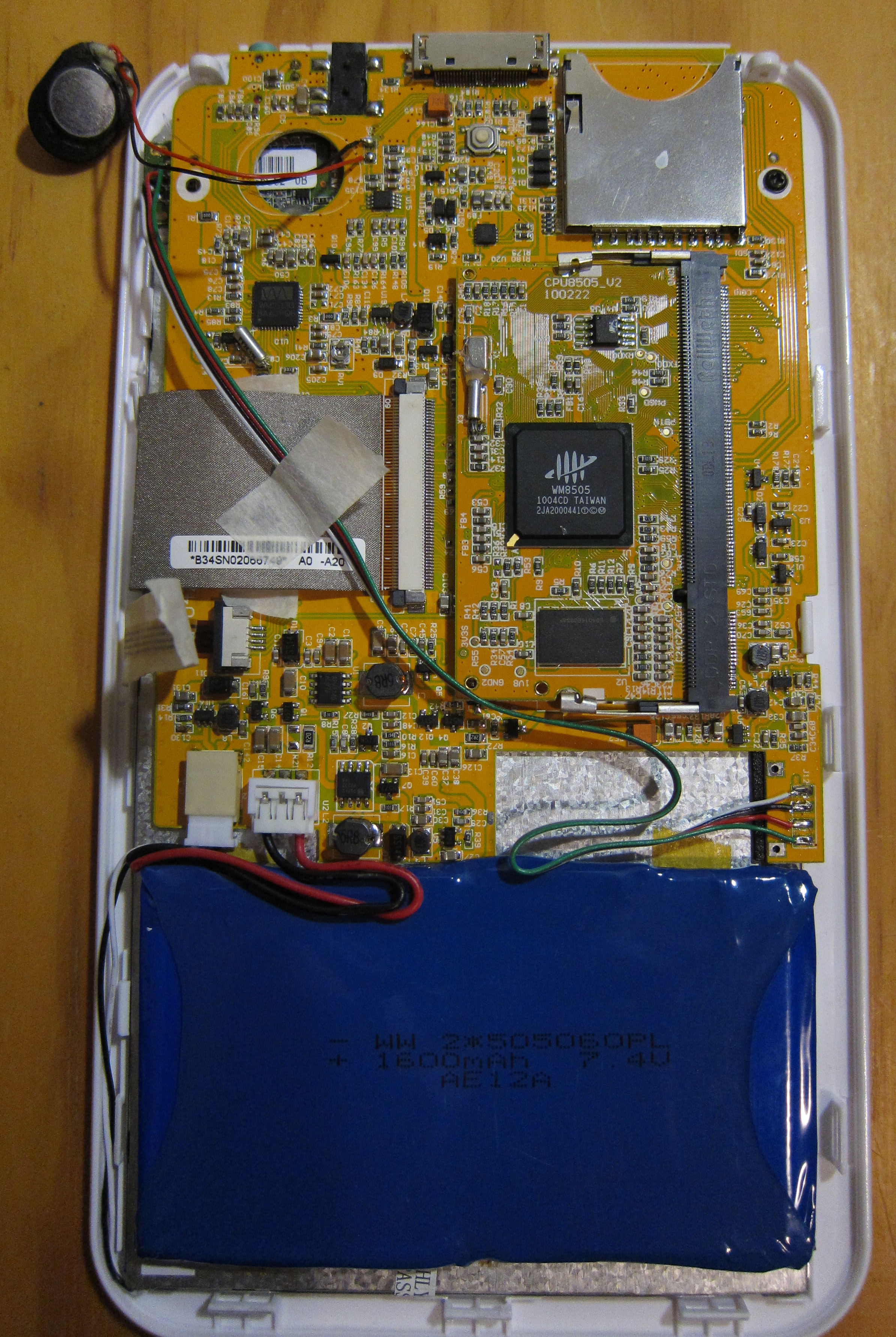
(Click through for a high-res version.)
You can see:
- Battery and backlight connectors bottom-left
- Internal USB soldered to pads bottom-right (leading up to the USB WiFi module, installed top left.)
- LCD and touchscreen ribbon connectors on the left side.
- Main CPU daughterboard in DIMM socket.
CPU Board
Here’s some shots of the CPU daughterboard:
![]()
![]()
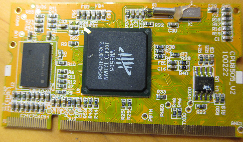
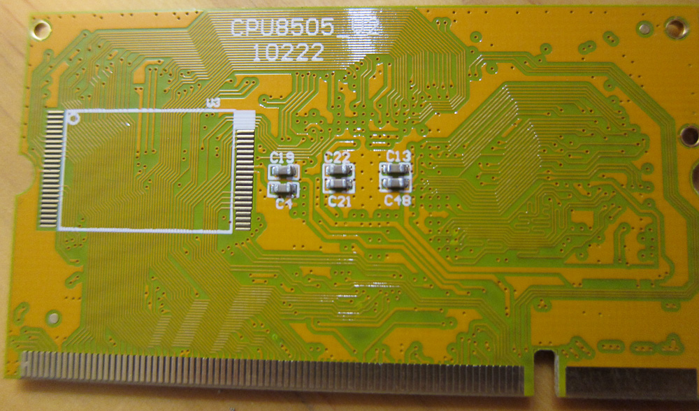
The board is hosting a VIA/Wondermedia WM8505 SoC. Datasheet shared here (courtesy Slatedroid, again.
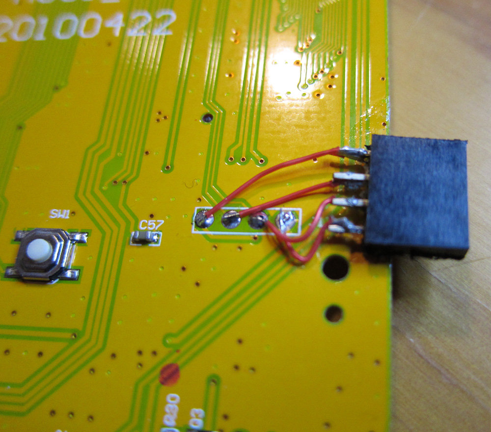
Serial Connector
J17 on the back of the board is a RvTTL (3.3v) serial port. 115200 8N1. Pinout, left to right, is Vcc Tx Rx Gnd.
I didn’t take any photos of it before I soldered on my serial port, but here it is after:
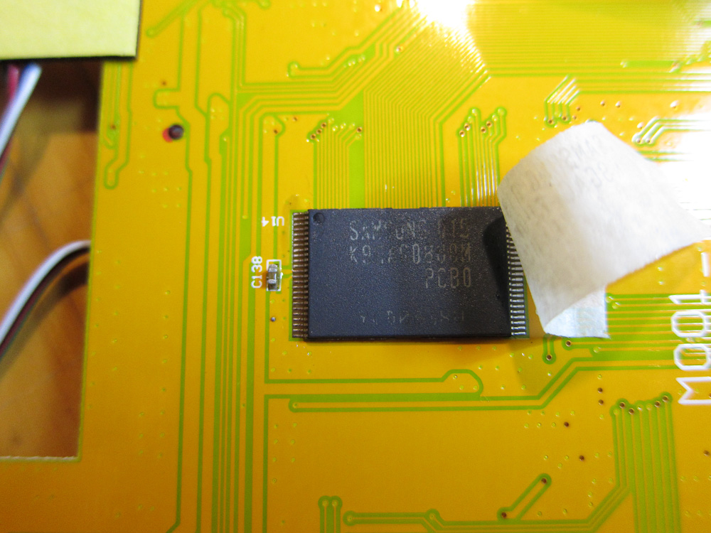
The only other interesting thing I saw on the back of the board was the 2Gb NAND flash:
Boot logs
Once you have the serial port connected, you can grab some log data easily (and you also get a root shell once startup completes.)
EDIT: As of firmware release 1.7.4, no more automatic root shell on serial console. It’s still a boot console, but for root you need to log in… Poor show, Eken.
Standard kernel boot log, plus some /proc entries
Log of a factory upgrade via SD card
I meant to capture and post some of the ‘logcat’ Android log output as well, from standard startup, but it doesn’t look like I kept any.

[...] Part Two: Teardown & serial console. [...]
Try to use UART too on my GOME Flytouch, use baud rate at 115200 8N1. But I’m always get junk, do you know why this happen?
Anyway Gus, can you tell me about the cabling? I use same as this http://www.lammertbies.nl/comm/info/RS-232_null_modem.html#noha
it only use 3 pinout, I don’t know the Vcc connected to where.
Thanks,
NO NO NO! DO NOT USE RS-232!!
The tablets have 3.3v LVTTL (aka RvTTL) serial ports. RS-232 is 12v, not compatible and could possibly fry the board!
There are converter chips that will convert RS232 voltage levels to LVTTL for you.
However, by far the easiest way to get LVTTL is to get an old mobile phone data cable. I have a whole bunch I’ve picked up from op shops (aka thrift stores) because people threw them out, but you can still get them new on ebay for a couple of bucks. Here’s a good page with some model numbers and a description of how to rewire one:
http://buffalo.nas-central.org/wiki/Use_a_Nokia_Serial_Cable_on_an_ARM9_Linkstation
For mine, I’ve only wired Rx Tx and Gnd. Vcc is not a required connection for most of the mobile phone style USB< ->Serial cables.
Good luck.
Ah, thank you, you saved my day, maybe I’m in luck not to frying my board
Since I did not have that phone data cable, so I build circuit from here: http://www.sparkfun.com/commerce/product_info.php?products_id=133 on top of Breadboard and now everything work well.
Hi. My M001 was damaged after an unsuccessful firmware update. Now he does not start, the screen goes black, sometimes the screen flashes when tightening the power button.
How can I use the serial port to insert the boot files in the flash memory?
Another thing, what kind of connector should I solder on the motherboard to get root access and what cable I use to connect the device to pc?
Thank you!
ok, i have dissasembled my bricked m001, tomorrow i will find my old nokia cable and sold cable into the mainboard (tx with tx or tx with rx??? sorry for the question[...]), but i have no idea what is the next move… i want to know what data (and where to find this) i need to write to memory, what soft i need to write data and all for revive my m001
thanks for all,i think your work is very useful for a lot of people!!!
Slideman/jose (I’m guessing you two are the same person?):
- Serial cable goes tx< ->rx rx< ->tx. I recommend testing the connection before you solder anything in place, just in case you have it backwards (have learned this the hard way.)
- While you have it apart, be careful not to flex the board or damage anything. I think these boards are pretty fragile, mine now has a variety of “quirks” that are probably caused by me tearing it down so many times.
- If your M001 is completely bricked (ie no “Android logo” boot screen) then it’s possible part of the bootloader (either or both of W-Load and u-boot) has been corrupted in the flash. If this is the case, the serial cable cannot save you. The only way to fix the machine would be to rewrite the flash directly or via JTAG, and AFAIK there is no known way to do that on the M001. Sorry.
- However, the only way to be sure is to plug in the serial cable and look at the boot log. If you want to see what the normal output from W-load and u-boot looks like, please see the boot log that’s linked from the post.
- It is possible the bootloader is not corrupt, but something else is, and you’ll find yourself dropped to a W-load or a u-boot console (if it boots past this stage, you can press any key during the boot process to drop to the u-boot console, as well.)
- If the bootloader does work, you may get some clues as to what went wrong by trying a firmware upgrade from the SD card and looking at the console output as it runs.
- Do the power lights come on as expected when you power your M001 up? Does it make any sounds?
Good luck.
.
- Angus
Hi. When I turn on the tablet, nothing appears on screen. Sometimes the screen flashes. The only thing visible is the red light on, indicating that the device is connected.
The device does not boot and does not read the sd card. When I turn off the tablet, it happens immediately, without having to hold the power button for several seconds.
The behavior of the device is looking for a switch light bulb, turns on and off, without any response from the tablet.
I’ll have to write the boot files directly into flash, I think.
Do you know a link with instructions to build a Jtag cable?
Is there a way to connect the cable to the device?
Thank you for your attention.
PS: I am not Jose.
hi, no, i’m not slideman, bit i have same error, press start and red light on, nothing more. as i comment i need to know what program need to use with jtag to try to read memory and see what is wrong. sorry for my english and thanks for all
Slideman/jose – Noone has identified JTAG pins on the board, so I don’t think you’ll have any luck with it unless you can track them down (if they exist).
If I were you, I’d connect the serial cable and see how far the boot process gets. If the bootloader is corrupt then I’m afraid the cheapest and easiest option is probably to buy a new tablet.
Then again, if you’re lucky and the bootloader is still there then you can probably unbrick it.
ahh sorry i was confused with the serial connector that you put i was thinking that this was the jtag!!!. ok, but my question is that when i make the connection like you, what soft can i use to read/write flash???
jose – if it works, you’ll find yourself able to drop into an interactive u-boot prompt. If you google u-boot you’ll find the command guide.
Also, if you look in the scriptcmd file that comes in the upgrade (tail -c +73 scriptcmd) then you’ll see all of the u-boot commands that the upgrade runs to reflash various sections, which should give you some idea what’s going on.
Your first step is still to find out if you have u-boot running at all, and how far the boot process is actually getting.
good and bad notices, serial connected, this is the good
only this is shown:
WonderMedia Technologies, Inc.
W-Load Version : 0.17.00.01
ethaddr…………found
W-Load loading…
i can’t do nothing no???
Hello,
I have a big problem, I updated my tablet M001 EKEN with SlateDroid version and all went well. but when I rebooted my tablet, I forgot to change the folder SCRIPT and I turned off the system, but unfortunately too late. Now when it starts, it displays the boot page of Android. I think he lost the bootloader. Question: Is it possible with the USB connector, to directly program the VIA WM8505? otherwise possible, with the mounting RS232, to directly program the VIA WM8505? if so, do you have the software programming of the bootloader program? thank you for your help.
Someone find a solution?
I have my M001 inthe state of turning on and off with red light but nothing else.screen flasjh for few milisecond and off.
Anyway to unbrick yet?
Thank you
Do you think trying to load linux will help?
Thanks
[...] upgrades and reflashes work. U-boot is also capable of interacting with the user via the built-in 3.3v serial port, if you solder some wires to [...]
Hi folks:
I’ve posted a summary of what I know about unbricking:
http://projectgus.com/2010/08/unbricking-wm8505-based-tablets/
Please, no more “I have a brick” comments on this blog post. Feel free to ask questions here about the serial port itself.
[...] of hooking up a JTAG interface. To do this requires a sacrificial CPU daughterboard (the one shown here under the 'CPU Board' heading.) Does anyone want to mail me one, for the greater good? All results [...]